[!] The blog has moved [!]

The blog has moved to http://carlitoscontraptions.com/.

You will be redirected to the new URL in 5 s. Sorry for the inconvenience.

December 31, 2007

Tensegrity and more

Based on the DIY Ornaments Weekend Projects Podcast my brother and I did some tensegrity and paper structures.

I'm particularly proud of the Popsicle sticks tensegrity structure since it is much stronger and cool looking than the straws one.

(note the upgraded upcoming POV display on the background)

Also, I got a new camera for Christmas, a nice Samsung s850, so now I can make some great pictures and video without needing to borrow a camera or whatnot (I'm really happy about it).
Here is a random picture from this great camera:

BTW, the Samsung s850 works very well under Linux!

December 26, 2007

The Battery Problem

Many devices require batteries but do not absolutely require to be absolutely portable. Since batteries are expensive and don't last for very long, it could be a would idea to add a wall power adapter connector to such devices. This would allow you to use the electricity from the mains to power a usually battery powered device.

I did precisely that to my new Air Hog helicopter I got for Christmas (I now, I'm a bit old for toys, but although I did not ask for it, I'm got I got it ). This small helicopter is lots of fun, but batteries (at least the rechargeable alkaline I use) last for about two flights (the helicopter must be charges by the remote in order to be able to fly for about 20 minutes).

Adding a power adapter connection to some device doesn't require many materials. You only need: a power adapter (duh), its corresponding connector, and some wire.

Once you have all materials, simply locate the ground and V+ nodes on the circuit (usually the black and red wires respectively) and solder the connector to them. Then make a nice hole on the device to make it stick out if necessary and you're ready to go.

Make sure your power adapter matches the voltage of the device and always verify all voltages with a voltmeter. If you exceed the expected voltage levels for the device you can be pretty sure to fry it.

(note the cool paper counterweight on the helicopter's nose)

December 24, 2007

Volume Limiter

What to do when a young child listens to very loud music on his headphones?
  1. Educate him: by explaining that he must reduce the time he is exposed to loud sounds depending on how loud they are, and how an over exposure to loud sounds could lead to permanent hearing loss. This is the best approach.
  2. Build a headphones volume limiter (i.e. the geeky solution).
I decided to build a volume reducer when my girlfriend told me she bought an inexpensive mp3 player (with no software volume limiter) for her little cousins, and that she learned he always sets the volume as loud as possible when listening to music (which worries his parents).

I had the idea of building a device that would interface with the headphones to the mp3 player (or any other audio device) and that would reduce the volume so it would become impossible to set it too loud.

I see basically two ways of doing this:
  1. To build a device that would clip (easiest) or reduce (trickier) the headphone's signal as soon ans it goes beyond a preset amplitude. I think this can be done with a couple of transistors and would be a good solution.
  2. To build a device that always decreases the volume by reducing the headphone's signal amplitude. This can be easily done with resistors but would waste energy and the volume reduction would vary depending on the headphones impedance.
Since I am a bit short on time (it must be done for Christmas) and since I think educating the child would be a much better solution to this problem, I went with the second design choice: inserting a resistor in series with the headphones in order to decrease the signal amplitude by creating a simple voltage divider.

Materials
This little project requires very few materials:
  • A couple of resistors. Their value depends on the headphone's impedance.
  • An old lipstick for the casing
  • A piece of perf board. Not really required but helps to make it more robust (it's going to be used by a child, so it must be sturdy)
  • A jack plug and a jack socket.
  • A piece of wire.
Construction
Simply solder the jack socket to the perf board (which should be cut to fit inside the gutted lipstick ) and put a resistor in series for each channel (left and right). Then connect the jack plug to the resistors and to ground by using the wire.

I drilled a hole on one end of the lipstick so the jack socket would fit tightly and stick out from it. The wire with the jack plug goes out of a hole on the other end of the lipstick.

At first, I chose to use a 10 Ohms resistor for each channel since I figured that the headphone impedance would be around 16 Ohms at DC. Later, I found out that 10 Ohms wasn't enough , so I added another 10 Ohms resistor in series on each channel, making the total resistance per channel 20 Ohms.

This means that with 16 Ohms headphones, the resulting volume would be 16/(16+20) = 44% of the original volume.

I know this volume reduction technique is very wasteful in terms of power and not very elegant, but it works fine and makes the very loud sounds just a bit more tolerable.

Finally, I used some isolating tape to make the construction a bit more resilient to children.

September 11, 2007

IR Detector

Besides my POV display, I'm trying to do a robot that detects obstacles using IR light. In order to make it easy to work with IR light, I built a very simple IR detector based on this article.

General Idea
An IR signal is "seen" by a reverse biased IR diode which produces an electrical signal according to the light intensity. This signal is then amplified trough a transistor which powers an ordinary LED. This means that the LED will light up when the IR diodes receives some IR light (from a TV remote for instance).

Materials
  • An IR Diode (I got mine from an old TV set)
  • An LED (a yellow one in my case)
  • A 1k Ohms resistor
  • A 50 Ohms resistor (two 100 Ohms resistors in parallel)
  • A BJT (I used the 2N3904, but any common BJT should work with the right biasing)
  • An old 9V battery (for the casing)
  • A new 9V battery (for power)
The Circuit

Construction Notes
I built the circuit by soldering the components together without using a PCB and enclosed it in an old 9V battery.

I used a battery as the casing because it is free, it looks cool, and it includes a battery clip.
The battery's cap is actually a battery clip that can be soldered to the circuit in order to connect it to another 9V battery.
When using a battery as a case, keep in mind that:
  • the inside of the battery should be insulated (with blue masking take in my case)
  • it is a good idea keep one or two of the AAAA batteries (that can be found inside the 9V battery) and use them to keep the top and bottom caps in place (make sure they are insulated two).

August 29, 2007

DIY Birthday Gift (a.k.a. Nail Puzzle)

Hypothetical situation: Let's suppose tomorrow is your friend's birthday and you forgot to get him/her a present. Also, let's assume you have no money whatsoever, all nearby stores are closed and he/she doesn't like things that come from the garbage.

What to do?
(a) You don't give him any present at all (second best option).
(b) You make a gift yourself (best option).
(c) You go into exile.

I chose "b". Below, instruction on how to make a quick and nice puzzle.

Materials
  • 19 big nails
  • a piece of wood
Tools
  • hammer
  • sand paper
  • sanding machine (particularly useful, but optional)
  • glue
  • drill
  • jig saw
In order to build a nice puzzle that will...well puzzle your friend for a while, especially if he/she is an engineering student, do as follows:
  1. Cut a large piece of wood that will become the main board
  2. Cut a small block that will stand and the nail stand.
  3. Glue them together so they look nice and the nail stand is not in the way
  4. Drill holes of equal depth on the small wood block so 18 nails can stand separately in each hole
  5. Plant a nail in the middle of the board and make sure it is nice and vertical.
  6. If you have some printable labels you can print the game instruction and stick them on an empty spot on the wood board. Make sure you sand everything well before applying the labels.
  7. It should look like the picture below.
Game Instructions: Put all 18 nails on the central nail. The resulting structure should be stable.
This means they should all be placed so that they only touch the central nail's head and maybe each other.

Game Solution: You can find the puzzle solution here.

Now enjoy your new puzzle. _

August 19, 2007

Arduino POV Prototype - Part 2

I polished up the code for my Arduino POV display and I think it is now ready to be shown to the world!

The source code for the POV display can be downloaded here.

The parameters in the code can be changed in order to display other images besides of the default arrows.

Data

The displayed image is stored in the data string. Each drawing is divided in frames (i.e. one frame for each letter of a word) and each frame is divided in columns. The image to be displayed must be encoded into 1s (ON) and 0s (OFF) and each value must be stored in the data string in the order illustrated below.

The duration of each column (i.e. how much time they stay ON), the spacing between frames and the spacing between images are set respectively by the integers timer1, timer2 and timer3. Keep in mind that their values depend on the rotation speed.

Finally, the number of frames and their length is set respectively by frame_num and frame_len.

Arrow (>):
  • timer1: 3
  • timer2: 15
  • timer3: 0
  • data: {1,0,0,0,0,1, 1,1,0,0,1,1, 0,1,1,1,1,0, 0,0,1,1,0,0}
  • frame_len: 4
  • frame_num: 1
"Alan" (my brother's name):
  • timer1: 3
  • timer2: 15
  • timer3: 13
  • data: {1,1,1,1,1,1, 1,0,0,1,0,0, 1,0,0,1,0,0, 1,1,1,1,1,1, 1,1,1,1,1,1, 0,0,0,0,0,1, 0,0,0,0,0,1, 0,0,0,0,0,1, 1,1,1,1,1,1, 1,0,0,1,0,0, 1,0,0,1,0,0, 1,1,1,1,1,1, 1,1,1,1,1,1, 0,1,1,0,0,0, 0,0,0,1,1,0, 1,1,1,1,1,1}
  • frame_len: 4
  • frame_num: 4

Sinewave (or girly flower):
  • timer1: 3
  • timer2: 3
  • timer3: 0
  • data: {0,0,1,0,0,0, 0,1,0,0,0,0, 1,0,0,0,0,0, 1,0,0,0,0,0, 0,1,0,0,0,0, 0,0,1,0,0,0, 0,0,0,1,0,0, 0,0,0,0,1,0, 0,0,0,0,0,1, 0,0,0,0,0,1, 0,0,0,0,1,0, 0,0,0,1,0,0}
  • frame_len: 12
  • frame_num: 1
E = MC^2:
  • timer1: 2
  • timer2: 10
  • timer3: 22
  • data: {1,1,1,1,1,1, 1,0,0,1,0,1, 1,0,0,1,0,1, 1,0,0,1,0,1, 1,0,0,1,0,1, 0,0,0,1,0,1, 0,0,0,1,0,1, 0,0,0,1,0,1, 0,0,0,1,0,1, 0,0,0,1,0,1, 1,1,1,1,1,1, 0,1,0,0,0,0, 0,0,1,0,0,0, 0,1,0,0,0,0, 1,1,1,1,1,1, 0,1,1,1,1,0, 1,0,0,0,0,1, 1,0,0,0,0,1, 1,0,0,0,0,1, 0,1,0,0,1,0, 0,1,0,0,1,0, 1,0,0,1,1,0, 1,0,1,0,1,0, 0,1,0,0,1,0, 0,0,0,0,0,0}
  • frame_len: 5
  • frame_num: 5

August 17, 2007

Arduino Launcher for the KDE menu

The Arduino software is good and works very well under Linux. Nevertheless, it doesn't create a menu item when installed and it can be tricky to create one for those who are not very used to Linux (like me).

In order to add a KDE menu launcher for the Arduino software, open the KDE Menu Editor, create a new item and put
cd /opt/arduino-0007/; ./arduino
in the Command field. Also, make sure that Run in terminal is checked and replace /opt/arduino-0007/ by your own installation path.

I'm sure there are thousands of other ways of doing this (including many than only require a few commands in the terminal) but at least this ways is pretty simple and and can be done without knowing that much about Linux.

August 13, 2007

Arduino POV Prototype

This is my first attempt to create a persistence of vision (POV) display using the Arduino. The ultimate goal is to mount it on my bike wheel and have it display nice things while I ride. But, for now, it consist of an array of 6 LEDs mounted on a turning rig I made From scrap material.

Materials for the rig:
  • 2 old cell phone batteries (found in the garbage) that serve as a counterweight
  • A piece of metal (from an old photocopier) that constitutes the turning blade
  • A fan motor from some sort of broken power supply I found in the UdeM garbage
  • A piece of plastic that makes the base (also from the photocopier)
  • A plastic poster edge (the things used to hold paper posters) that I found in the garbage (it is used to cover the sharp edges of the blade).
  • A heavy metal block that stabilizes the contraption (since it tends to oscillate a bit when it's turning)
  • A cable with a switch from an IKEA lamp I found in the garbage
  • Lots of cable ties
Materials for the POV circuit:
  • A small breadboard (it came with an electronics magazine)
  • 6 red high power LEDs
  • 6 1 k Ohms resistors
  • A 9V battery w/ battery older
I think the pictures are pretty self explanatory.

The LEDs are directly connected to the pins 2 to 7 of the Arduino and their current is limited by the resistors.
The entire circuit is powered by the 9V battery.

So far I have done some simple patterns for the display and I'll upload the code soon (it still needs some polish)

I expect to add more LEDs to the design as soon as I get the patterns and the overall code working fine.

August 03, 2007

Arduino Clones

For my birthday my girlfriend got me 4 Bare-Bone Boards (from the Modern Devices Company). The boards are fully featured Arduino clones. The only difference with the original Arduino (AFAIK) is that they are cheaper (15$ each or less) and better suited for breadboard connection.

What's an Arduino?
Arduino is an open-source electronics prototyping platform based on flexible, easy-to-use hardware and software. It's intended for artists, designers, hobbyists, and anyone interested in creating interactive objects or environments.

- The Arduino Website -

Note that these clones are cheaper because they require a USB-to-TTL serial cable (20 $). The advantage of this approach is that the cable includes the required USB controller chip and can be used to program many boards. In short, you only need to pay for the USB connectivity once and get to use it on as may boards as you want.

Also, I was very (really very) pleased to see that the Arduino software works perfectly under Linux and that there are instructions for installation on all major distros (including Ubuntu) in the Arduino website.
Update: Here are a few extra shots done with my new camera. This is the new Rev. D board.

July 15, 2007

Fully Featured Media Center on a Budget

Recently my girlfriend got rid of her cable television connection and moved to a cheaper (almost free) and fully featured media center solution (i.e. Xbox + Xbox Media Center).
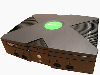
Meterials
  • Xbox (not 360)
  • Xbox remote (not required, but useful)
  • Xbox Controller (usually comes with the Xbox)
  • Xbox memory card (8 MB is enough)
  • Modded Xbox from a relative (for a one time use)
  • MechAssault game disk
  • Softmod installer
  • Computer, router, high speed internet connection, electricity (you should already have these).
General Idea
The idea is to unlock the Xbox, which is basically a very cheep computer, in order to run the very excellent and free Xbox Media Center (XBMC), a very advanced media player. Then, the Xbox can be use to watch videos, play music, stream content from the internet, and more (all in the comfort of the living room).

I know XBMC has been around for many years now, but I think is a good idea to write a post to show off its incredible features and explain how to get it.

How to do it
First, get all the materials. My girlfriend and I got a second hand Xbox complete with a remote and a controller for 100$ at Comptant.com after searching around a lot for a good deal. Then, I got a Mechassault original (not the platinum edition) game disk for 9$ and an 8MB memory card for 10$ (all second hand). So we spent a total of 120$ (much cheaper than any commercial media center).

In order to get the Xbox to run homebrew software (i.e. software that is not signed by Microsoft such as XBMC) its security system must be disabled. This can be done by installing a softmod (witch doesn't require any hardware modification of the gaming system).

I choose to use the Krayzie Ndure SOFTMOD Pack that can be downloaded from the torrents. The idea is to get one of the game saves from this package (depending on which game you want to use) into the memory card and then into the Xbox. In order to get the MechAssault save to the memory card I used my own (hard)modded Xbox: I copied the game save folder to the E:\UDATA folder trough FTP and then I copied the game save (named Linux Installer) to the memory card by using the original Xbox dash. If you don't have access to a modded Xbox, there are other ways of getting the save to the Xbox such as Action Replay or building a USB adapter.

Now, the easy part. Once you have the game save in the memory card, connect the Xbox to the router (as you would connect any other computer to it), plug the card into the controller, and turn the console on. Then, in the Xbox dash, go to the memory menu and copy the game save to the Xbox hard drive (hdd). Afterwards, insert the MechAssault disk, select the campaign menu entry, and then select "Linux Installer". This will take you to a dashboard that will guide you through the installation of the softmod. Simply follow the steps (back up the eeprom and install the softmod) and in less than 2 minutes you will have a modded Xbox with your dashboard of choice (you can chose between EvolutionX or UnleashedX).

Now you can play game backups, run unsigned software and much more. Note that you need to update the Xbox dash to the latest version in order for the softmod installer to work properly. This can be done by using the "Live" menu entry in the Xbox dash.

Now that the Xbox is modded, you need to install XBMC. I used the latest Pimped version that comes with all the features you would want (codecs, scripts, visualizations, skins) and can be downloaded from the torrents. Once you have it downloaded and unziped, you must copy the XBMC folder to E:/apps in the Xbox's hdd (the usual applications folder) through FTP (sending files trough FTP is the standard way of installing application onto the Xbox).

For FTP communication with the Xbox you can use any FTP client you want (I use Konqueror). In order to connect to the Xbox you need to know its IP address (which is normally shown on the main menu of the evolution dashboard) and its user name (Xbox) and password (Xbox). for further information in connecting to the Xbox trough FTP, please see this site.

Once the XBMC folder has been copied to E:/apps, reboot the Xbox (this will update the dashboard menu), and go to the applications menu an chose Xbox Media Center in order to start this wonderful program. You can also set it to start automatically (I recommend this) by following this guide.

Now that you have XBMC up , running and connected to the internet you can:
  • play videos/music/pictures stored on any computer connected to router trough SMB (windows network) or stored in the local hd (it support almost all audio/video formats known to man).
  • Play PAL and NTSC DVDs/VCDs from any region.
  • Stream media from the internet, including tv shows, podcasts, movies, music, music videos, and much more.
  • Check the weather forecast.
  • And tons of other cool things.
Some Screenshots(note that the top and bottom black borders are not shown in the TV screen)

Final Remarks
Don't forget to configure XBMC to adjust it to your needs (I recommend using the MC360 skin). For further information about using XBMC please consult the user's manual.

You have now a very powerful media center that is far superior than any of the commercial alternatives I know. Enjoy.

Besides, you may also want to install some other great application such as dvd2xbox, which allows to backup entire games to the Xbox hdd, and boXplorer, an excellent file manager. You can get them from the usual places.

June 09, 2007

Debouncer v2

I wrote a quick debouncer code in VHDL that I thought people could enjoy and may be useful for FPGA projects. For more info on debouncers see this post.

As shown in the block diagram below, it takes as inputs a switch signal (SW_IN) and a clock signal (CLK) and outputs a signal SIG.

When SW_IN goes high, the module outputs a once-clock-cycle wide pulse on the next clock rising edge. Then it waits for 8388607 clock cycles (~ 0.17 s when clocked @ 50MHz). This is illustrated in the state transition diagram below.

You can download the code here.