[!] The blog has moved [!]

The blog has moved to http://carlitoscontraptions.com/.

You will be redirected to the new URL in 5 s. Sorry for the inconvenience.

September 25, 2006

Wireless Skype Phone

At first, I saw on this site someone who modified his wireless phone in order to connect it to his computer, transforming it in a wireless speaker and microphone. I though it was kind of cruel to modify a working phone that way.

Some time later, my girlfriend gave me a broken wireless phone that belonged to her parents. I saw it was a nice phone so I tried to repair it but I couldn’t. Basically it worked fine, you can play with the menu, store phone numbers, dial, call, the sound quality is good, the reception is ok and the battery life is satisfactory. It has only one small problem: you can’t hang up. So unless you’re planning to call someone and talk to him indefinitely, it is kind of useless. So I decided to make it into a cordless internet phone.

General Idea

I wanted to have a wireless phone that connects to my computer speakers and microphone so I can use it as a PC wireless headset. Among other things, it coild be used to talk over Skype.

In order to achieve this goal, I hard wired the voice inputs and outputs of the wireless phone to my computer.
Materials:
  • 1 cordless phone (mine is a VTech 2428)
  • 2 3.5mm plugs (headphone plugs)
  • 1 switch
  • 1 screw
  • 1 washer
  • some cables

Getting it done

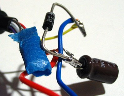
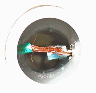
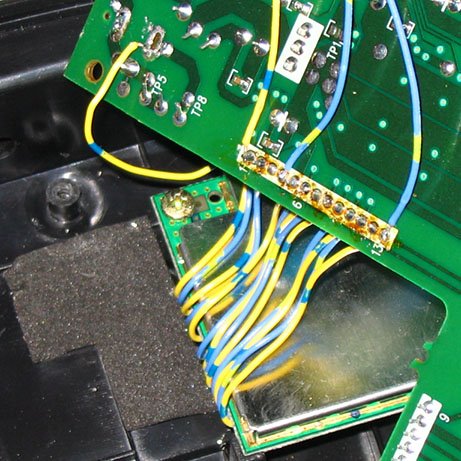
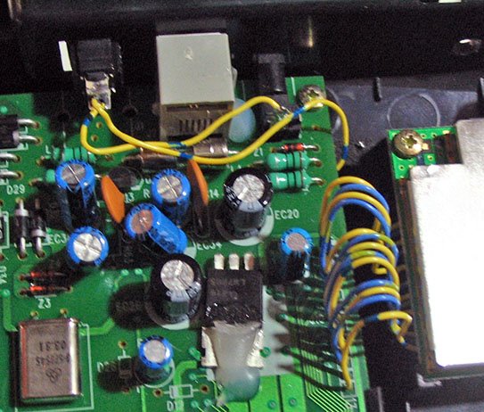
First, I looked for the part of the phone circuit that manages the RF transmission. This was easy since the RF transmitter and the phone PCB are separated. The two parts are connected together with a grey cable ribbon which, at least in my case, is of very poor quality and broke very quickly. I replaced the ribbon with many pieces of individual wires. The result is much stronger and, most importantly, very colourful.


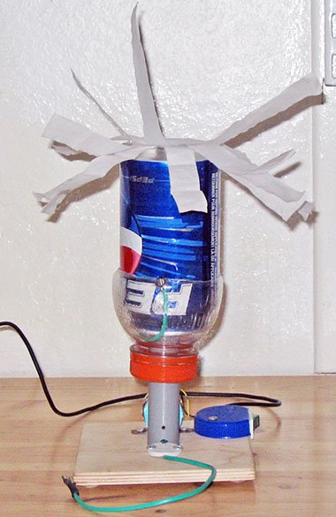
Having found the RF transmitter, I needed to discover which of its pins carries the sound signals to and from the wireless headset. So, I probed the pins of the RF transmitter in order to know which one is ground, which one carries the sound to the speaker and which one brings the sound from the microphone by using an old toy that generates a sort of music (you could use any sound generator but keep in mind you could fry it).

I figured the the ground pin had to be the top or the bottom one, since it makes sense to put the there (at least to me). To discover the speaker pin, I played a sound between two pins and tried to listen to it at the receiver until I hear it. For the microphone pin, I played a sound at the receiver's microphone and connected a speaker between two pins until I hared the sound.

Finally, I discovered that, for the VTech 2428 (and I presume for all the other VTech products that use the same transmitter) the first pin (top of the pin row in the picture) on the RF receiver is ground (which makes sense), the fourth is for the speaker and the last (bottom) is for the microphone.

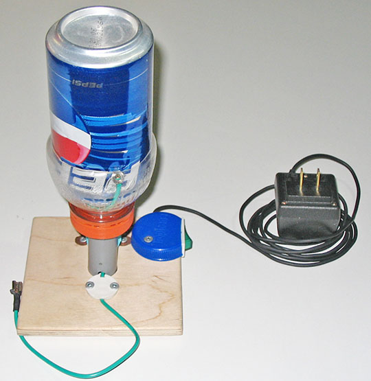
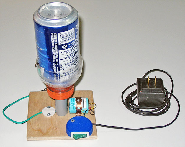
Once the pins were discovered I simply soldered the 3.5mm plugs to them and secured the cables to the box using a big washer and a screw in order to ensure the connections wont break if the cables are pulled (don't worry for the space, this thing is mostly empty). By the way, I got my cables from a PC I found in the garbage so they were already color coded and labeled as “phone” and “mic”.

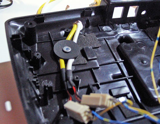
Also, I drilled a hole on the back of the case in order to get the cables out of the phone.

Since I don’t use the phone a lot, I installed a switch on it so I can turn it off. In order to interrupt the power flow into the device I desoldered the power connector, turned, the + leg up and soldered it back in so the + leg is not in contact with the PCB any longer. Then I soldered a switch between the leg and the PCB. I removed the phone line-out connector in order to fit the switch in its place. The line-in remains there and fully functional.

After putting it back together the phone was done and ready to use, It just needs to be plugged in to a computer. As a final remark, the sound quality is very good, both for incoming and outgoing signals. It can be used to talk on Skype from anywhere in the house, as a wireless spy microphone, or even to listen to mp3s while working on some new project (the later uses are not recommended).
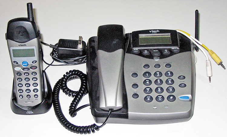

Drawbacks

Unfortunately, this hack doesn’t allow you to play the phone tones to the computer in order to dial or pick up Skype.


Future improvements:

I’m working on a ringer that will ring the phone when there is a Skype call. My idea is to use a square wave generated in the computer that will travel down the unused speaker channel(since the phone is mono) to switch on a ringer signal (90Vpp sine wave).

I would also like to add a pick up function but that seems difficult since I don’t want to use any other connection besides the ones already available.

September 23, 2006

Save the Internet

These are just a few words about net neutrality, don't worry, I'll be back with more contraptions soon.

Please, visit www.savetheinternet.com


September 15, 2006

Bottle Cap PC Thermometer

Based on a circuit I found in this website, I built a very simple thermometer. The major thing I added to the original design is a nice case.

Materials:
  • 1 Diode
  • 1 Thermistor
  • 1 Capacitor
  • 1 Serial cable (or plug)
  • 2 Plastic bottle caps (one slightly bigger than the other)

The CircuitI salvaged all the parts from old electronics (found in garbage) so they were free. All the parts are very easy to find except for the thermistor. I did not get precisely a thermistor but a very close approximation to it. In fact, I’m not very sure of what it is that I used.

I just soldered the components together, no need of PCB.

My Thermistor

I got the thermistor form a broken drinking water dispenser /cooler.

The relationship between the temperature and resistance in an usual thermistor is mostly linear. For my thermistor, the lower bound for the linear region of the resistance-temperature relation is 11°C. Below this point, its resistance goes to infinity (is doesn’t allow any current to pass). I suppose this is used to stop cooling the water when it gets at the desired 11°C temperature. I haven’t yet found an upper bound for the liner region.

Anyways, the only problem is that it can’t measure temperatures below 11°C.

The Case

To build a nice looking case, I simply used two plastic bottle cap (from a Propel and Powerade bottles) that my girlfriend brought me from the recycling bin at her job (a gym).

These two caps happen to fit perfectly one inside the other. So I simply cut a hole for the cable and drilled another for the probe (MT). I placed the circuit (properly insulated with tape, of course) inside, closed it and the thermometer was done.

The Software

In order to run use the thermometer you need a small program. I used the program provided in the original project but it wouldn’t be hard to right a new one or to improve the existing one.

September 05, 2006

Cheap Van de Graaff Generator

A Van de Graff generator (named after its inventor) is a high voltage generator. It basically loads a spherical hollow conductor with static charges which brings the conductor to a very high (or very low) potential. In other words, it is the metal sphere on a vertical tube that makes your hair raise when you touch it. For more info on this, please consult this Wikipedia article.

Inspired by many web sites (1 2 3 4 5), I decided to build my own Van de Graaff generator. It will not raise your hair but it is fun, easy to build, and very cheap. Also it doesn’t require any glue (I always try to avoid glue).

Materials
  • A soft drink can.
  • A Gatorade bottle (or any bottle that, at some point, has a bigger diameter than the can’s diameter).
  • A small piece of tubing ( PBC if you’re fancy or just a cardboard roll from aluminium foil).
  • A block of wood.
  • A small DC motor (from a toy).
  • A switch (not mandatory).
  • A wide rubber band.
  • Another rubber band (a standard one)
  • Some pieces of thick cable.
  • Some pieces of thin cable.
  • Some screws.
  • A 3.7V power adaptor that I found in the garbage (or some batteries and a battery holder).
  • A small nail.
  • A small plastic cylinder from a wire connector.
  • A plastic bottle cap.
  • A metal or plastic strap.

General Idea

The idea is to have a belt moving inside a tube (4 and 5). The belt rubs two metal combs (2 and 7). One of them is connected to ground (7) and the other one to a metallic sphere(2). The belt takes the charges from ground and carries them to the sphere. The sphere gets charged and voila! you get a high voltage.
The design

In this design (this is not my design), the wide rubber band is the belt, the soda can is an approximation to the metal sphere, the combs are done with a spread stripped wire, and the a PBC tube is used as… a tube. The belt is hold in place by a nail insulated with a piece of plastic at one end, and by the motor’s shaft at the other end. All these pieces are attached to a wood base for stability.
Putting it together
The base:
The wood block will serve as a base. Drill a hole of the same diameter than the tube trough the center of wood block. Then sand it to make it nice and smooth. The tube should fit tight in the hole (see pictures).

The sphere:
Open the top of the soda can using a knife, tough scissors, a very powerful laser or a small nuclear explosion.

Cut the Gatorade bottle at it’s horizontal indentation so the can fits tight in it (see pictures).

Drill a hole of the same diameter than the tube at the center of the Gatorade bottle cap so it fits tight around the tube (see pictures).

The tube:
Cut a piece of PBC (or cardboard) tube so it is a bit longer (~ 1cm longer) than your rubber band at rest.

Drill a small hole through the tube (slightly bigger than the nail’s diameter) near the top of it.

Drill a larger hole (~5mm diameter) at the place where the motor shaft is inserted into the tube (at around (thickness of the block of wood + motor radius) from the lower end of the tube, ~ 2 cm in my case). The shaft and the nail must be parallel.

Opposite from the motor hole, drill another 5mm hole but lower. The hole should be a (wood thickness) from the bottom.

The combs:
Take two pieces (~15 cm and ~10cm) of thick insulated copper wire (inside, it must not be a solid copper rod but many small wires) and remove the plastic insulation from both ends (or just from one end because your lucky and you have some sort of connector at the other end).

For both wires, spread one of the striped ends in order to form a kind of comb.

The Motor:
If you’re unlucky and your motor’s casing is broken, build a new case around it so the motor is firmly held together. I used a calcium tablets package for this purpose

Assembly
  1. Insert the tube in the base hole.
  2. Put the motor’s shaft in its hole and attach the motor to the base with a metal (or plastic) strap and two screws.
  3. Insert the tube into the caped Gatorade bottle (the cap should face down).
  4. Insert the nail and its insulation in the tube’s top hole. The wide rubber band should hang from it (inside the tube).
  5. Attach the comb end of the shortest wire to the top of the tube with a rubber band (I know, I should have found a better way to attach it. Anyways, it turns out to be very robust). The comb should gently caress the rubber band.
  6. Insert the can and make sure the other end of the wire makes a good contact with it.
  7. Pull the rubber band from the bottom of the tube so it hangs between the motor shaft and the nail. I think the motor shaft should be insulated but mine is not and it works perfectly well.
  8. Pass the other comb end wire trough the remaining hole (5mm one at the bottom) so it caresses (lots of caressing going one) the bottom of the rubber band. Fasten the wire to the base with a piece of plastic and some screws, for instance.
  9. Add a switch, a power source (you can case the switch with a plastic bottle cap).
  10. Voila! It’s done (you'll have to tinker with it until everything works fine, but that shouldn't be too hard).
Now enjoy your Van de Graaff generator (try putting some tissue strips or small strings on it and turning it on).