[!] The blog has moved [!]

The blog has moved to http://carlitoscontraptions.com/.

You will be redirected to the new URL in 5 s. Sorry for the inconvenience.

October 13, 2006

La Cucaracha

--------[!]--------
Update: La Cucaracha has got lots of attention lately (mainly thanks to Alan Parekh from HackedGadgets). I found some of its cousins built by 7 year olds. See them at ArtBots Robots.
------------------
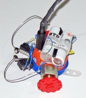
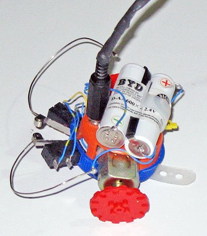
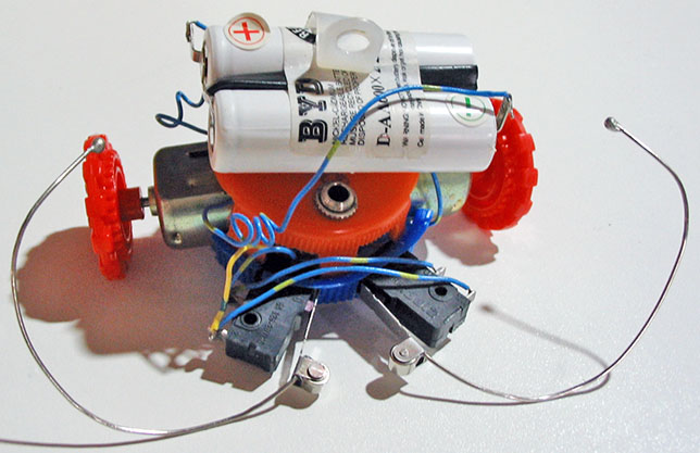
This is a small and very simple robot that requires no electronics. It is inspired on La Coccinelle. They both work according to the same principle, but their bodies and wheels are different. Also mine uses rechargeable batteries so I don’t need to buy new ones after just a few hours of usage.

Materials:
  • 2 big plastic bottle caps (much like the PC Thermometer)
  • 2 Wire ties
  • 1 screw
  • 2 DC Motors
  • 2 toy wheels
  • 1 switch (a small one so it fits on the bottle cap)
  • Some cables
  • 1 Cable holder
  • 1 Rechargeable battery pack w/ charger
  • 1 3.5 mm audio jack (male and female)
  • 2 paper clips (regular size)
  • 2 SPDT Switches (commonly found in printers)

Main Idea

The idea is to construct a robot that can move around and that will backup and change the direction of the motion when it hits an obstacle.

Putting it together
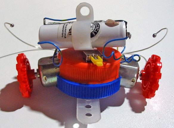
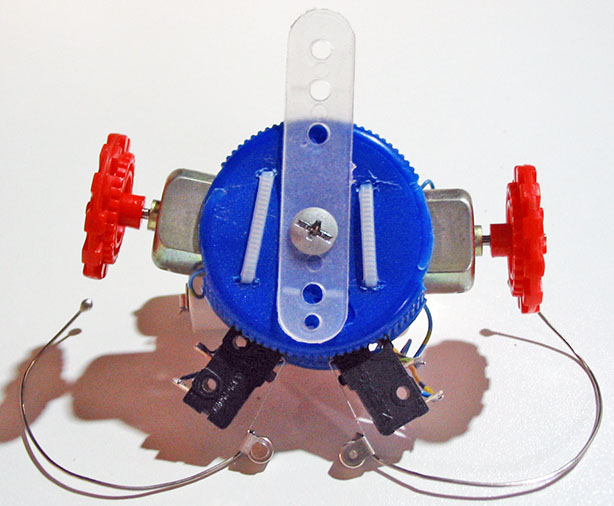
  1. Cut two diametrically opposite holes on the side of the caps so the motors fit in there. Chose one of the caps as your base cap (the one thats goes on bottom).
  2. Pierce two small holes on the top of the base cap in order to tie the motors to the cap using the small cable ties.
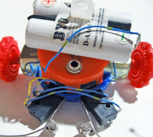
  3. Cut two more holes spaced by about 1.5 cm so the switches fit in tightly (seeing the pictures help visualizing this).
  4. Drill a hole in the center of both caps with the same diameter as your screw.
  5. Install the switch and the female audio jack on the top bottle cap.
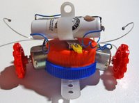
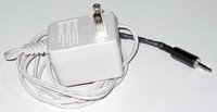
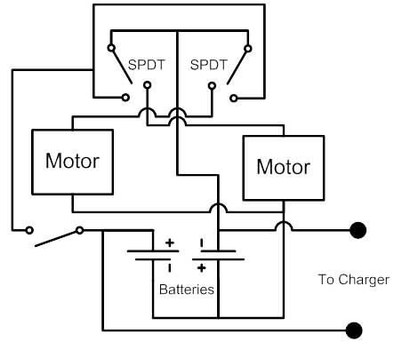
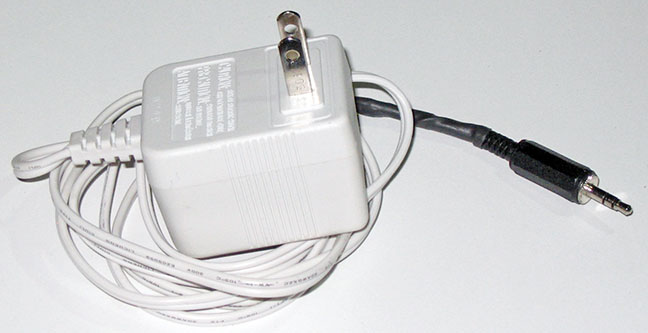
  6. Connect everything together as shown in the circuit diagram. I used the audio jack to make the charger connection. The charger is simply a 3V power adapter connected in series with a diode in the + terminal.
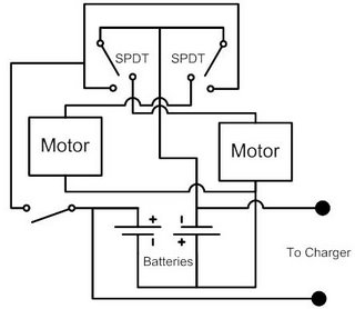
  7. Solder the paper clips to the SPDT blades and add a little solder blob on each paper clip end so they look more like antennas.
  8. Test to see if the circuit works properly. When the robot is switched on, both spindles should spin so it goes forward. If an antenna is pushed, the spindle on the opposite side (left spindle if right antenna) should spin backwards.
  9. Fasten the motors to the base cap using the cable ties and secure the other cap on top of it using the screw. Also secure the cable holder using the same screw on top of the top cap, this serves as a battery holder.
  10. Insert the toy wheels on each motor spindle. You can also add a piece of plastic for stability under the base cap.
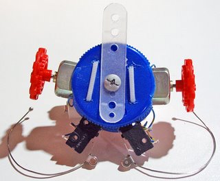
It’s done! Now you have a small robot that will go around your house bumping on whatever is on its path.

October 11, 2006

Coming Soon

Some projects I will be writing on soon:
  • La Cucaracha, a robot without electronics
  • Cheap Bench Power Supply, see this picture
  • Laptop USB Lamp
  • CD Lamp², the obvious evolution of the CD lamp
  • Cornstarch Pet, a small project based on this experiment
  • Ultra Cheap XBOX USB adaptor.
  • Skype phone ringer.

October 08, 2006

Make Your Girlfriend Happy For 0.25$

I saw in this site (try this one if the link is broken) that we can build a coin ring using a spoon, a drill, a Dremel and some metal polish. Immediately, I wanted to do one.

Materials:
  • An ordinary 0.25$ coin (Canadian in my case)
  • Lots of patience
Making it happen
Warning: your family and specially your dog could become agitated if you hit a coin with a spoon during an entire day.
I started by hitting my coin on its edge with a spoon. I used a small metal plate a found laying on the street as a rigid surface for the hitting. After about 2 hour of lots of hitting and almost no change I tried using a small hammer. It bended the coin faster but the results were a little deceiving. In the original site pictures, you see the inside of the coin bending uniformly outward., Instead I got flat edge and a smashed inside. After about two more hours of hitting I switch to a normal full-sized hammer.

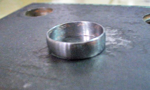
I hit the coin until I got it to the right diameter (my estimation of my girlfriend’s finger diameter) and then I hit it with the spoon once again. The spoon flattens the edge surface making it smoother (which means less sanding and polishing afterwards). Also the spoon allows for fine control over the shape of the ring.

Once I got the edge to the right shape and diameter, I drilled a hole on the coin. I then used a screw to secure the coin to a drill and polished the outside of the rim by making it spin very fast. I used a fine sandpaper at first and some Brasso and a cloth afterwards.

Removing the inside of the coin was the most difficult part since I don’t have any clamp that can hold it without damaging it. Also, I could not preserve the outer part of the coin's inside as shown in the original site since mine was completely smashed. Anyways, in the end I removed the body of the coin usind some files and polished the inside of the newly born ring.

I gave the shiny (except for some dark spots caused by my inaccurate hitting) ring to my girlfriend who was very happy with it. I was happy to see it fitted her finger (although it was a bit loose).

Later, I discovered that the guy in the site used a silver coin (i know it is an obvious fact), which I suppose is easier to bend than my 94% steel coin.

Anyway, the end result is quite pleasing and nobody will believe you built a ring from a coin by hitting it with a spoon (unless you explain them how to proceed and show them pictures, people are very skeptical).

And yes I know, it is illegal to break money. This is why this never happened , you simply imagined visiting this site and seeing this project.

September 25, 2006

Wireless Skype Phone

At first, I saw on this site someone who modified his wireless phone in order to connect it to his computer, transforming it in a wireless speaker and microphone. I though it was kind of cruel to modify a working phone that way.

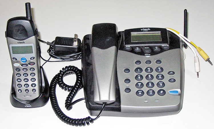
Some time later, my girlfriend gave me a broken wireless phone that belonged to her parents. I saw it was a nice phone so I tried to repair it but I couldn’t. Basically it worked fine, you can play with the menu, store phone numbers, dial, call, the sound quality is good, the reception is ok and the battery life is satisfactory. It has only one small problem: you can’t hang up. So unless you’re planning to call someone and talk to him indefinitely, it is kind of useless. So I decided to make it into a cordless internet phone.

General Idea

I wanted to have a wireless phone that connects to my computer speakers and microphone so I can use it as a PC wireless headset. Among other things, it coild be used to talk over Skype.

In order to achieve this goal, I hard wired the voice inputs and outputs of the wireless phone to my computer.
Materials:
  • 1 cordless phone (mine is a VTech 2428)
  • 2 3.5mm plugs (headphone plugs)
  • 1 switch
  • 1 screw
  • 1 washer
  • some cables

Getting it done

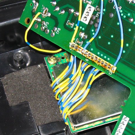
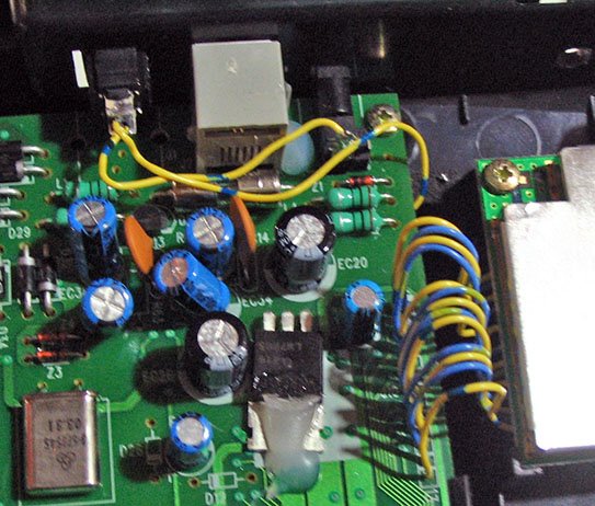
First, I looked for the part of the phone circuit that manages the RF transmission. This was easy since the RF transmitter and the phone PCB are separated. The two parts are connected together with a grey cable ribbon which, at least in my case, is of very poor quality and broke very quickly. I replaced the ribbon with many pieces of individual wires. The result is much stronger and, most importantly, very colourful.


Having found the RF transmitter, I needed to discover which of its pins carries the sound signals to and from the wireless headset. So, I probed the pins of the RF transmitter in order to know which one is ground, which one carries the sound to the speaker and which one brings the sound from the microphone by using an old toy that generates a sort of music (you could use any sound generator but keep in mind you could fry it).

I figured the the ground pin had to be the top or the bottom one, since it makes sense to put the there (at least to me). To discover the speaker pin, I played a sound between two pins and tried to listen to it at the receiver until I hear it. For the microphone pin, I played a sound at the receiver's microphone and connected a speaker between two pins until I hared the sound.

Finally, I discovered that, for the VTech 2428 (and I presume for all the other VTech products that use the same transmitter) the first pin (top of the pin row in the picture) on the RF receiver is ground (which makes sense), the fourth is for the speaker and the last (bottom) is for the microphone.

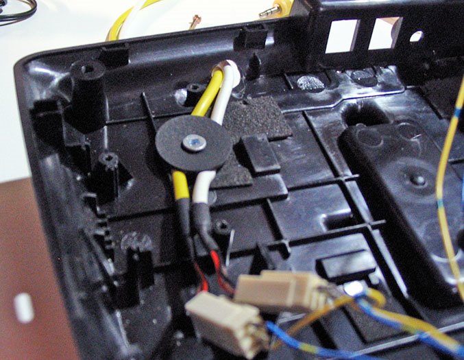
Once the pins were discovered I simply soldered the 3.5mm plugs to them and secured the cables to the box using a big washer and a screw in order to ensure the connections wont break if the cables are pulled (don't worry for the space, this thing is mostly empty). By the way, I got my cables from a PC I found in the garbage so they were already color coded and labeled as “phone” and “mic”.

Also, I drilled a hole on the back of the case in order to get the cables out of the phone.

Since I don’t use the phone a lot, I installed a switch on it so I can turn it off. In order to interrupt the power flow into the device I desoldered the power connector, turned, the + leg up and soldered it back in so the + leg is not in contact with the PCB any longer. Then I soldered a switch between the leg and the PCB. I removed the phone line-out connector in order to fit the switch in its place. The line-in remains there and fully functional.

After putting it back together the phone was done and ready to use, It just needs to be plugged in to a computer. As a final remark, the sound quality is very good, both for incoming and outgoing signals. It can be used to talk on Skype from anywhere in the house, as a wireless spy microphone, or even to listen to mp3s while working on some new project (the later uses are not recommended).


Drawbacks

Unfortunately, this hack doesn’t allow you to play the phone tones to the computer in order to dial or pick up Skype.


Future improvements:

I’m working on a ringer that will ring the phone when there is a Skype call. My idea is to use a square wave generated in the computer that will travel down the unused speaker channel(since the phone is mono) to switch on a ringer signal (90Vpp sine wave).

I would also like to add a pick up function but that seems difficult since I don’t want to use any other connection besides the ones already available.

September 23, 2006

Save the Internet

These are just a few words about net neutrality, don't worry, I'll be back with more contraptions soon.

Please, visit www.savetheinternet.com