
This is a simple project that requires some skills in cutting and shaping wood and lots of old CDs.
 The Idea
To make a nice looking lamp that uses CDs to shade the light. The lamp should be composed of two overlapping columns of CDs sandwiched between identical pieces of wood. It should be very energy efficient and output a reasonable amount of light (which implies LEDs).
Materials
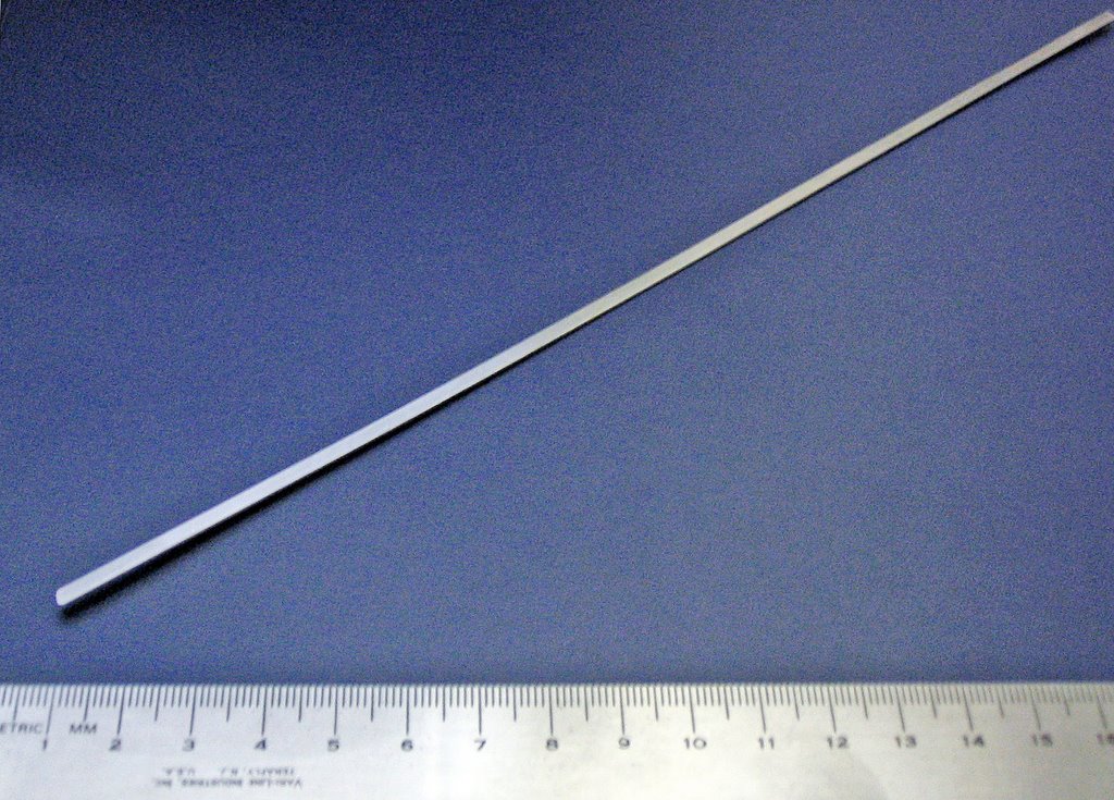
- 6 metal rods (I got them from an old photocopier I found in the garbage)
- 4 special washer for holding the rods (from the same photocopier)
- lots of CDs
- 2 pieces of wood (from an old drawer I found in the garbage)
- 10 LEDs (6 white and 4 blue in my case)
- A resistor (for current limiting for the LEDs)
- A switch
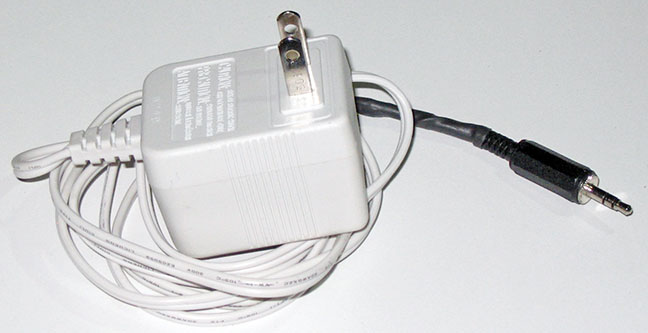
- A 5V power adaptor
- A calcium tablets package and a bottle cap (for the switch casing)
- 4 protective rubber pads.
Preparation
Trace the layout on the wood. The layout consists of two circles spaced by ~12 cm so when the CDs are centered at the center of the circles, the CD holes don't overlap (while the rest of the CD does overlap). Since I had very small pieces of wood, there was very little room for error (in fact, there was no room for error). I traced the layout using a compass and a ruler (pretty standard), and I cut the wood using a jigsaw.
The lamp is symmetrical so the base and the top should be identical.
 It is important to thoroughly sand the wood so it is smooth and nice to the touch. It is good to use a large grit sandpaper first and a fine one to give it a nice finish.
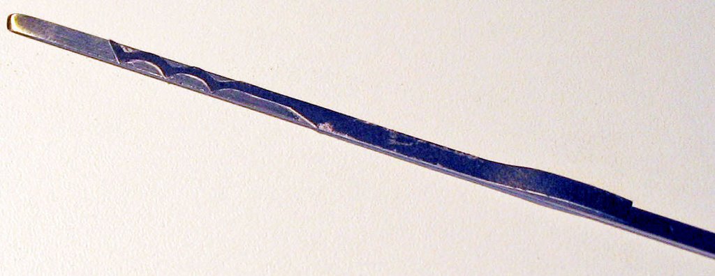
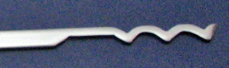
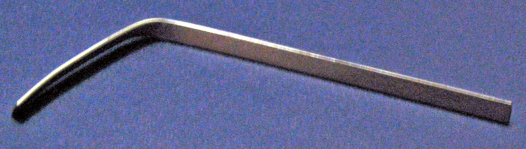
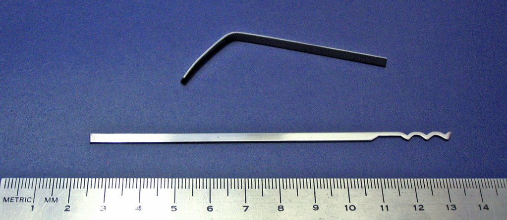
Drill the holes for the metal rods. Four of the rods will hold the exterior of the CDs and should go trough the good. The two remaining rods hold the CDs at their intersection. should not go through the wood (they should be only deep enough so the metal rods stay in place once the the top is in place).
 The rods hold the CDs inside the lamp and keep the base and the top pieces of wood together.
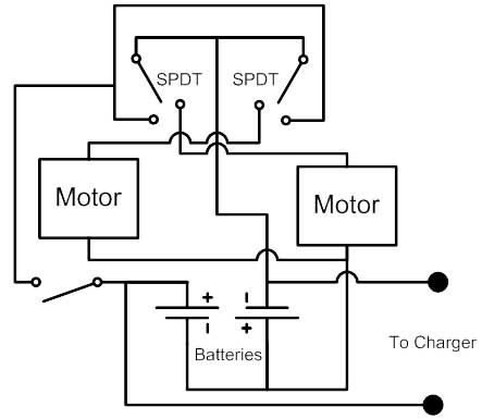
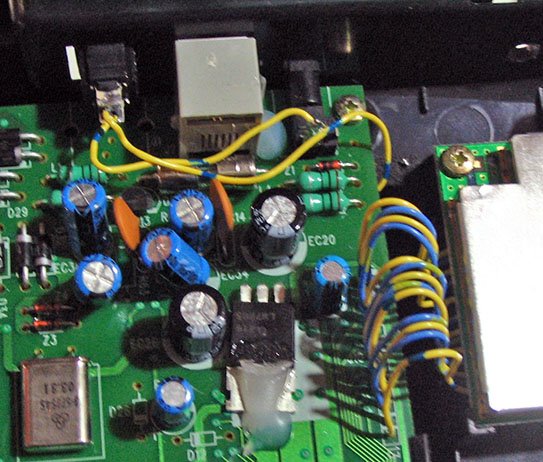
The light will be provided by two 5 LEDs arrays in parallel as seen in the following circuit schematic.
 I alternated blue and white LEDs for the arrays soldered together in order to form a column that fits inside the CD holes. Remember to use a current limiting resistor for the LEDs (see this current limiting resistor calculator).
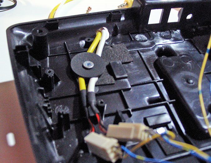
The switch should go on the power adaptor wire. I was not lucky enough to have a switch ready made for that propose so I built a case for the switch using a calcium tablet case and a bottle cap.

 Assembly
Place the exterior rods in the appropriate holes on the Top piece and place the special washer at the base. The alternating from one side to the other, place CD pairs until the top of the lap is reached (forming two overlapping columns). The CD pairs are composed of two CDs back to back (the shiny face on the outside).
 Then, place the two LED arrays and connect them to the power source and the switch. Make sure the LEDs are pointing to the from of the lamp.
Once the LEDs are in place the smaller metal rods and the bottom can be placed. Fasten the bottom using the washers.
Place some rubber pads on the bottom so the lamp does not scratch delicate surfaces.
The lamp is done. Enjoy!


Note: no CDs where harmed during the construction of this lamp.


