Bench power supplies (PS) are very handy for testing electronics because they are reliable, stable and secure. It supplies variable voltage in a fairly large range, and detects when you are darning too much current from it or when its outputs are shorting, turning itself off elegantly instead of burning or overheating like some cheap power adaptors. Nevertheless, this kind of equipment cost around 200$ (usually more), which is very expensive (at least to me).
My version is much cheaper, I estimate it costs 8$ (4% of the retail cost). Of course, it has some limitations, but not that many.
Enough chitchat, let's get started.
Materials:
- 5 female surface-mount banana connectors (I had to buy them @ 8 for 12$)
- A computer power supply (from the old computer I found)
- 2 LEDs + surface mount (I got them from the same computer)
- A switch (I had it lying around)
- A resistor (use this calculator to get a value for your resistor)
- 4 protective rubber pads (they give a feminine touch)
- A power cord (Duh…)
Putting it together
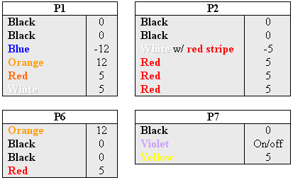
Of course, my computer PS is not standard (GPC 145-4001), so I couldn’t find its specifications anywhere. So, I did a bit of reverse engineering (poking around) and figured out the pinout shown in this table:
 Note: for P7 (P1, P2,... are the actual name written on the plugs) the yellow wire outputs 5V when the power supply is plugged in regardless of it being on or off. Also, when the violet wire is grounded, the power supply turns on. It goes off as soon as the violet wire is not grounded. Finally, the maximum power output is 150W, pretty respectable.
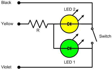
In order to control the power supply and show when it is on/off and plugged-in, I attached the following circuit to P7:

This works very simply: the yellow LED turns on when the PS is plugged to the mains and the green LED turns on when the switch is closed and the PS turns on.
 I desoldered all the wires (P1, P2 ad P6) from the PS, leaving just one for each output (5V, -5V, 12V, -12V, and GND). Desoldering them is better than cutting for obvious reasons (less clutter, more reliable, etc). The output wires will be attached to banana connectors mounted on the PS case in order to make them more accesible (make sure the connectors are isolated from the case).
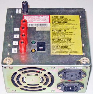
In order to pack everything inside the PS case, I drilled 5 holes for the banana connectors, 2 smaller holes for the 2 LEDs, and drilled and filed a rectangular hole for the switch (I know, it would have been much simpler to use a round switch). Since everything fits very tightly in the case, the holes placement must be carefully planned so the added parts won’t interfere with the PS (i.e. stop the fan, make undesired connections between the components).
The last step is to put everything together and close the case.
 The newly born power supply will turn off nicely when you short its outputs or when the load exceeds its maximum power output capacity (i.e. when you plug a big motor or a power tool to it). By combining the outputs (DC) you can get 5V (GND to 5V), 7V (5V to 12V), 10V (-5V to 5V), 12V (GND to 12V), 17V (-5V to 12V), and 24V (-12V to 12V).
As a finishing touch I added rubber pads on the bottom so it doesn’t scratch my desk and I labeled the outputs using a labeling machine (pretty fancy).
 Future improvements
I will add a variable voltage divider in order to easily get other useful voltages out of it, such as 3.3V and 9V.


2 comments:
stupleOca-de Jeremy Hearshman click here
orciocremic
Post a Comment